


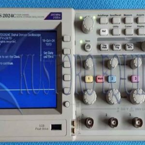
Tektronix DPO2014 Digital Phosphor Oscilloscope
$1,000
Model : DPO2014 Oscilloscope

Description
Tektronix DPO2014 Digital Phosphor Oscilloscope
Tektronix DPO2014 Digital Phosphor Oscilloscope provides powerful performance and benefit-packed tools for simple and fast analysis and debugging of mixed signals. Deep, usable record length on all channels allows you to capture long windows of signal acitvity while maintaining fine timing resolution. A variable low-pass filter enables you to see signal details to the oscilloscope’s full bandwidth. Tektronix DPO2014 Digital Phosphor Oscilloscope also offers serial trigger, decode analysis options and many more features needed to simplify and speed debug of complex designs.
The MSO2000 and DPO2000 Series digital phosphor oscilloscopes (DPOs) deliver the performance and tools you need to visualize your signals and find answers quickly. Tektronix DPO2014 are the first oscilloscopes to provide 1 M points of usable record length on all channels, serial trigger and decode analysis options, a variable low-pass filter that also allows you to see signal details to the oscilloscope’s full bandwidth and all in a compact form factor.
Tektronix DPO2014 provides a complete set of triggers, including runt, logic, pulse width/glitch, setup/hold violation, serial packet, and parallel data to help quickly find your event. With up to a 1 Mpoint record length, you can capture many events of interest, even thousands of serial packets, Tektronix DPO2014 is a single acquisition for further analysis while maintaining high resolution to zoom in on fine signal details.
From triggering on specific packet content to automatic decode in multiple data formats, the DPO2014B provides integrated support for a broad range of serial buses: I2C, SPI, CAN, LIN, and RS-232/422/485/ UART. The ability to decode up to two serial and/or parallel buses simultaneously means you gain insight into system-level problems quickly.
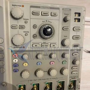
Ease of Use Features
- Wave inspector controls provide easy navigation and automated search of waveform data
- FilterVu variable low-pass filter allows for removal of unwanted signal noise while still capturing high-frequency events
- 29 automated measurements, and FFT analysis for simplified WaveformAnalysis
- TekVPI probe interface supports active, differential, and current probes for automatic scaling and units
- 7 in. (180 mm) widescreen TFT-LCD color display
- Small footprint and lightweight – only 5.3 in. (134 mm) deep and 7lb. 14 oz. (3.6 kg)
Connectivity
- USB 2.0 host port on the front panel for quick and easy data storage
- USB 2.0 device port on rear panel for easy connection to a PC or direct printing to a pictBridge®-compatible printer
- Optional 10/100 ethernet port for network connection and video out port to export the oscilloscope display to a monitor or projector
Applications
- Design and debugging
- Design and debugging of mixed signals (analog and digital)
- Power Measurements
- Automotive Electronics
- Education and training
- Design and debugging of video circuits
Key Features Tektronix DPO2014:
- Sample rates up to 1 GS/s on all channels
- 1 Mega sample record length on all channels
- 5,000 wfm/s maximum waveform capture rate
- Suite of advanced triggers
- Serial Bus Trigger and Decode
- I2C, SPI, CAN, LIN, and RS-232/422/485/UART serial triggering, decode, and analysis options
- Wave Inspector® Navigation and Search provides unprecedented efficiency in waveform analysis
- FilterVu™ variable low-pass filter allows for removal of unwanted signal noise while still capturing high-frequency events
- 7 in (180 mm) bright, widescreen, TFT-LCD color display
- USB 2.0 on front panel for quick and easy data storage
- USB 2.0 device port on rear panel for direct PC control of oscilloscope using USBTMC or direct printing to any PictBridge® compatible printer
- Plug ‘n’ Play PC connectivity and analysis software solutions
- Optional LAN and VGA video ports
- TekVPI® Probe Interface supports active, differential, and current probes for automatic scaling and units
- Small footprint and light weight – only 5.3 in (134 mm) deep and 7 lb 14 oz (3.6 kg)
Specifications Tektronix DPO2014
| Characteristic | MSO2012
DPO2012 |
MSO2014
DPO2014 |
MSO2024
DPO2024 |
| Input Channels | 2 | 4 | 4 |
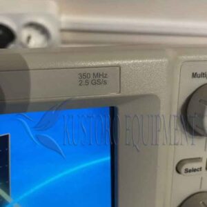
| Analog Bandwidth (-3 dB)*1 | 100 MHz | 100 MHz | 200 MHz |
| Calculated Rise Time | 3.5 ns | 3.5 ns | 2.1 ns |
| Hardware Bandwidth Limits | 20 MHz | ||
| Input Coupling | AC, DC, GND | ||
| Input Impedance | 1 MΩ ±2%, 11.5 pF ±2 pF | ||
| Input Sensitivity Range | 2 mV/div to 5 V/div | ||
| Vertical Resolution | 8 bits | ||
| Maximum Input Voltage, 1 MΩ | 300 VRMS with peaks ≤ ±450 V | ||
| DC Gain Accuracy (with offset set to 0 V) | ±3% for 10 mV/div to 5 V/div
±4% for 2 mV/div to 5 mV/div |
||
| Channel-to-Channel Isolation
(Any Two Channels at Equal Vertical Scale) |
≥100:1 at ≤100 MHz | 100:1 at ≤200 MHz | |
*1 Bandwidth is 20 MHz at 2 mV/div, all models.
Offset Range
| Range | 1 MΩ |
| 2 mV/div to 200 mV/div | ±1 V |
| >200 mV/div to 5 V/div | ±25 V |
Vertical System Digital Channels
| Characteristic | All MSO2000 Models |
| Input Channels | 16 Digital (D15 to D0) |
| Thresholds | Threshold per set of 8 channels |
| Threshold Selections | TTL, CMOS, ECL, PECL, User Defined |
| User-defined Threshold Range | ±20 V |
| Maximum Input Voltage | ±40 V |
| Threshold Accuracy | ±(100 mV +3% of threshold setting) |
| Maximum Input Dynamic Range | 80 Vpk-pk (threshold setting dependent) |
| Minimum Voltage Swing | 500 mVpk-pk |
| Input Impedance | 101 kΩ |
| Probe Loading | 8 pF |
| Vertical Resolution | 1 bit |
Horizontal System Analog Channels
| Characteristic | MSO2012/2014
DPO2012/2014 |
MSO2024
DPO2024 |
| Maximum Sample Rate (all channels) | 1 GS/s | |
| Maximum Record Length
(all channels) |
1 Mpoints | |
| Maximum Duration of Time Captured at Highest Sample Rate
(all channels) |
1 ms | |
| Time-base Range (s/div) | 4 ns to 100 s | 2 ns to 100 s |
| Time-base Delay Time Range | -10 divisions to 5000 s | |
| Channel-to-Channel Deskew Range | ±100 ns | |
| Time-base Accuracy | ±25 ppm | |
Horizontal System Digital Channels
| Characteristic | All MSO2000 Models |
| Maximum Sample Rate (when using any of channels D7-D0) | 1 GS/s (1 ns resolution) |
| Maximum Sample Rate (when using any of channels D15-D8) | 500 MS/s (2 ns resolution) |
| Maximum Record Length (all channels) | 1 Mpoints |
| Minimum Detectable Pulse Width | 5 ns |
| Channel-to-Channel Skew | 2 ns typical |
Trigger System
| Characteristic | Description |
| Main Trigger Modes | Auto, Normal, and Single |
| Trigger Coupling | DC, HF reject (attenuates >85 kHz), LF reject (attenuates <65 kHz), noise reject (reduces sensitivity) |
| Trigger Holdoff Range | 20 ns to 8 s |
| Trigger Signal Frequency Counter | Provides a higher accuracy means of identifying the frequency of trigger signals. Trigger Signal Frequency counter resolution is 6 digits. |
Trigger Sensitivity
| Characteristic | Description |
| Internal DC Coupled | 0.4 divisions from DC to 50 MHz
0.6 divisions > 50 MHz to 100 MHz 0.8 divisions > 100 MHz to 200 MHz |
| External
(Auxiliary Input) |
200 mV from DC to 100 MHz, 1X attenuation |
Trigger Level Range
| Characteristic | Description |
| Any Channel | ±4.92 divisions from center of screen |
| External
(Auxiliary Input) |
±6.25 V, 1X attenuation
±12.5 V, 10X attenuation |
Trigger Modes
| Mode | Description |
| Edge | Positive or negative slope on any channel or front-panel auxiliary input. Coupling includes DC, AC, HF reject, LF reject, and noise reject. |
| Pulse Width | Trigger on width of positive or negative pulses that are >, <, =, or ≠ a specified period of time. |
| Runt | Trigger on a pulse that crosses one threshold but fails to cross a second threshold before crossing the first again. |
| Logic | Trigger when any logical pattern of channels goes false or stays true for specified period of time. Any input can be used as a clock to look for the pattern on a clock edge. Pattern (AND, OR, NAND, NOR) specified for all analog and digital input channels defined as High, Low, or Don’t Care. |
| Setup and Hold | Trigger on violations of both setup time and hold time between clock and data present on any of the input channels. |
| Rise/Fall Time | Trigger on pulse edge rates that are faster or slower than specified. Slope may be positive, negative, or either. |
| Video | Trigger on line number, all lines, odd, even, or all fields on NTSC, PAL, and SECAM video signals. |
| I2C (optional) | Trigger on Start, Repeated Start, Stop, Missing ACK, Address (7 or 10 bit), Data, or Address and Data on I2C buses up to 3.4 Mb/s. |
| SPI (optional) | Trigger on SS, MOSI, MISO, or MOSI and MISO on SPI buses up to 10.0 Mb/s. |
| CAN (optional) | Trigger on Start of Frame, Frame Type (data, remote, error, overload), Identifier (standard or extended), Data, Identifier and Data, End of Frame, Missing ACK, or Bit Stuffing Error on CAN signals up to 1 Mb/s. Data can be further specified to trigger on ≤, <, =, >, ≥, or ≠ a specific data value. User-adjustable sample point is set to 50% by default. |
| RS-232/422/485/UART (optional) | Trigger on Tx Start Bit, Rx Start Bit, Tx End of Packet, Rx End of Packet, Tx Data, Rx Data, Tx Parity Error, and Rx Parity Error. |
| LIN (optional) | Trigger on Sync, Identifier, Data, Identifier and Data, Wakeup Frame, Sleep Frame, Errors such as Sync, Parity, or Checksum Errors. |
| Parallel (available on MSO models only) | Trigger on a parallel bus data value. |
Acquisition Modes
| Mode | Description |
| Sample | Acquire sampled values. |
| Peak Detect | Captures glitches as narrow as 3.5 ns at all sweep speeds. |
| Averaging | From 2 to 512 waveforms included in average. |
| Roll | Scrolls waveforms right to left across the screen at sweep speeds slower than or equal to 40 ms/div. |
Waveform Measurements
| Measurement | Description |
| Cursors | Waveform and Screen. |
| Automatic Measurements | 29, of which up to four can be displayed on-screen at any one time. Measurements include: Period, Frequency, Delay, Rise Time, Fall Time, Positive Duty Cycle, Negative Duty Cycle, Positive Pulse Width, Negative Pulse Width, Burst Width, Phase, Positive Overshoot, Negative Overshoot, Peak to Peak, Amplitude, High, Low, Max, Min, Mean, Cycle Mean, RMS, Cycle RMS, Positive Pulse Count, Negative Pulse Count, Rising Edge Count, Falling Edge Count, Area and Cycle Area. |
| Gating | Isolate the specific occurrence within an acquisition to take measurements on, using either the screen, or waveform cursors. |
Waveform Math
| Characteristic | Description |
| Arithmetic | Add, subtract, and multiply waveforms. |
| FFT | Spectral magnitude. Set FFT Vertical Scale to Linear RMS or dBV RMS, and FFT Window to Rectangular, Hamming, Hanning, or Blackman-Harris. |
Software
| Product | Description |
| NI LabVIEW SignalExpress™ Tektronix Edition | A fully interactive measurement software environment optimized for the MSO/DPO2000 Series, enables you to instantly acquire, generate, analyze, compare, import, and save measurement data and signals using an intuitive drag-and-drop user interface that does not require any programming.
Standard MSO/DPO2000 Series support for acquiring, controlling, viewing, and exporting your live signal data is permanently available through the software. The full version (SIGEXPTE) adds additional signal processing, advanced analysis, mixed signal, sweeping, limit testing, and user-defined step capabilities and is available for a 30-day trial period standard with each instrument. |
| OpenChoice®Desktop | Enables fast and easy communication between a Windows PC and the MSO/DPO2000 Series. Transfer and save settings, waveforms, measurements, and screen images. Included Word and Excel toolbars automate the transfer of acquisition data and screen images from the oscilloscope into Word and Excel for quick reporting or further analysis. |
| IVI Driver | Provides a standard instrument programming interface for common applications such as LabVIEW, LabWindows/CVI, Microsoft .NET, and MATLAB. |
| eScope | Enables control of the MSO/DPO2000 Series over a network connection through a standard web browser. Simply enter the IP address or network name of the oscilloscope and a web page will be served to the browser. |
Display Characteristics
| Characteristic | Description |
| Display Type | 7 in. (180 mm) liquid crystal TFT color display. |
| Display Resolution | 480 horizontal × 234 vertical pixels (WQVGA). |
| Waveform Styles | Vectors, Dots (In Video Trigger mode), Variable Persistence, Infinite Persistence. |
| Graticules | Full, Grid, Cross Hair, Frame. |
| Format | YT and XY. |
| Maximum Waveform Capture Rate | Up to 5,000 wfm/s. |
Input/Output Ports
| Port | Description |
| USB 2.0 High-speed Host Port | Supports USB mass storage devices and keyboards. One port available on front panel. |
| USB 2.0 High-speed Device Port | Rear-panel connector allows for communication/control of oscilloscope through USBTMC or GPIB with a TEK-USB-488, and direct printing to all PictBridge-compatible printers. |
| LAN Port | RJ-45 connector, supports 10/100Base-T (requires DPO2CONN). |
| Video Out Port | DB-15 female connector, connect to show the oscilloscope display on an external monitor or projector (requires DPO2CONN). |
| Auxiliary Input | Front-panel BNC connector. Input Impedance 1 MΩ ±2%. Max input 300 VRMS CAT II with peaks ≤ ±450 V. |
| Probe Compensator Output | Front-panel pins
Amplitude: 5 V Frequency: 1 kHz |
| Kensington Style Lock | Rear-panel security slot connects to standard Kensington-style lock. |
Power Source
| Characteristic | Description |
| Power Source Voltage | 100 to 240 V ±10% |
| Power Source Frequency | 45 to 65 Hz (90 to 264 V)
360 to 440 Hz (100 to 132 V) |
| Power Consumption | 80 W maximum |
| Optional TekVPI® External Power Supply (119-7465-xx) | Output Voltage: 12 V
Output Current: 5 A Power Consumption: 50 W |
Physical Characteristics
| Dimensions | mm | in. |
| Height | 180 | 7.1 |
| Width | 377 | 14.9 |
| Depth | 134 | 5.3 |
| Weight | kg | lb. |
| Net | 3.6 | 7.9 |
| Shipping | 6.2 | 13.7 |
| Rackmount Configuration | 4U | |
| Cooling Clearance | 2 in. (50 mm) required on left side and rear of instrument | |
Environmental
| Characteristic | Description |
|
Temperature |
|
| Operating | 0 ºC to +50 ºC |
| Non operating | -40 ºC to +71 ºC |
|
Humidity |
|
| Operating | High: 30 ºC to 50 ºC, 5% to 60% Relative Humidity
Low: 0 ºC to 30 ºC, 5% to 95% Relative Humidity |
| Nonoperating | High: 30 ºC to 55 ºC, 5% to 60% Relative Humidity
Low: 0 ºC to 30 ºC, 5% to 95% Relative Humidity |
|
Altitude |
|
| Operating | 3,000 meters (9,843 feet) |
| Nonoperating | 12,000 meters (39,370 feet) |
|
Random Vibration |
|
| Operating | 0.31 GRMS from 5 to 500 Hz, 10 minutes each axis, 3 axes, 30 minutes total |
| Non operating | 2.46 GRMS from 5 to 500 Hz, 10 minutes each axis, 3 axes, 30 minutes total |
|
Regulatory |
|
| Electromagnetic Compatibility | EC Council Directive 2004/108/EC |
| Safety | UL61010-1:2004;
CAN/CSA C22.2 No. 61010.1-04; EN61010-1:2001; Complies with the Low Voltage Directive 2004/108/EC for Product Safety. |
Package Includes :
- 1 – device Tektronix DPO2014 4 Channels 100MHz 1GSs Digital Phosphor Oscilloscope
- 1 – Translated Front-Panel Overlay
- 1 – OpenChoice Desktop Software
- 1 – Calibration Certificates Document
- 1 – Quality System Registration
- 1 – Power Cord
- 1 – User Manual
Additional information
| Lead Time | 5-7 days |
|---|---|
| Packaging | Box |
Brand
Tektronix


Reviews
There are no reviews yet.