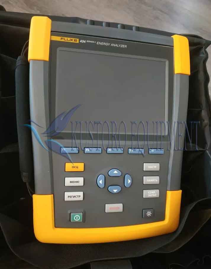
Fluke 434 Series II Three Phase Energy Analyzer
$3,350
Model : 434 Series II Analyzer

Description
Fluke 434 Series II Three Phase Energy Analyzer
Fluke 434 Series II Three-Phase Energy Analyzers offers the best in power quality analysis and introduce, for the first time ever, the ability to monetarily quantify energy losses.
The new Fluke-434-II helps locate, predict, prevent, and troubleshoot power quality problems in three-phase and single-phase power distribution systems. Additionally, these models feature revolutionary power quality and energy measurement functions that help facilities reduce electrical power consumption, and improve the performance and lifespan of electro-mechanical equipment. Below you will find brief descriptions of these new features.
Description Fluke 434 Series II
The Fluke 434 Series II Energy Analyzer is the ideal tool for energy logging. Utilizing the new Energy Loss Calculator function, the 434 II measures the fiscal cost of energy wasted due to poor power quality. This energy monetization capability identifies the most energy-wasteful areas of your facility, enabling you to identify energy saving solutions. Add basic power quality measurements to the package and you’ve got yourself one powerful troubleshooting tool.
Fluke’s patented Unified Power Measurement system (UPM) provides the most comprehensive view of power available, measuring:
- Parameters of Classical Power (Steinmetz 1897) and IEEE 1459-2000 Power
- Detailed Loss Analysis
- Unbalance Analysis
These UPM calculations are used to quantify the fiscal cost of energy loss caused by power quality issues. The MONITOR mode delivers a dashboard display of rms voltage, harmonics, flicker, interruptions, rapid voltage changes, swells, unbalance, frequency and mains signaling. The dashboard is updated live, showing compliance of each parameter to EN50160 limits or your own limits. Color-coded bars clearly show which parameters are inside (pass) or outside (fail) limits. During a monitor session, you can easily drill down to more detail of any parameter to view and capture its trend for a report.
Features
|
Specifications
| Model | Measurement range | Resolution | Accuracy | |
|
Volt |
||||
| Vrms (ac+dc) | 434-II | 1 V to 1000 V phase to neutral | 0.1 V | ± 0.5% of nominal voltage |
| Vpk | 1 Vpk to 1400 Vpk | 1 V | 5% of nominal voltage | |
| Voltage Crest Factor (CF) | 1.0 > 2.8 | 0.01 | ± 5 % | |
| Vrms½ | 434-II | 1 V to 1000 V phase to neutral | 0.1 V | ± 1% of nominal voltage |
| Vfund | 434-II | 1 V to 1000 V phase to neutral | 0.1 V | ± 0.5% of nominal voltage |
|
Amps (accuracy excluding clamp accuracy) |
||||
|
Amps (ac +dc) |
i430-Flex 1x | 5 A to 6000 A | 1 A | ± 0.5% ± 5 counts |
| i430-Flex 10x | 0.5 A to 600 A | 0.1 A | ± 0.5% ± 5 counts | |
| 1mV/A 1x | 5 A to 2000 A | 1A | ± 0.5% ± 5 counts | |
| 1mV/A 10x | 0.5 A A to 200 A (ac only) | 0.1 A | ± 0.5% ± 5 counts | |
| Apk | i430-Flex | 8400 Apk | 1 Arms | ± 5 % |
| 1mV/A | 5500 Apk | 1 Arms | ± 5 % | |
| A Crest Factor (CF) | 1 to 10 | 0.01 | ± 5 % | |
| Amps½ | i430-Flex 1x | 5 A to 6000 A | 1 A | ± 1% ± 10 counts |
| i430-Flex 10x | 0.5 A to 600 A | 0.1 A | ± 1% ± 10 counts | |
| 1mV/A 1x | 5 A to 2000 A | 1A | ± 1% ± 10 counts | |
| 1mV/A 10x | 0.5 A A to 200 A (ac only) | 0.1 A | ± 1% ± 10 counts | |
| Afund | i430-Flex 1x | 5 A to 6000 A | 1 A | ± 0.5% ± 5 counts |
| i430-Flex 10x | 0.5 A to 600 A | 0.1 A | ± 0.5% ± 5 counts | |
| 1 mV/A 1x | 5 A to 2000 A | 1A | ± 0.5% ± 5 counts | |
| 1mV/A 10x | 0.5 A A to 200 A (ac only) | 0.1 A | ± 0.5% ± 5 counts | |
|
Hz |
||||
| Hz | Fluke 434 @ 50 Hz nominal | 42.50 Hz to 57.50 Hz | 0.01 Hz | ± 0.01 Hz |
| Fluke 434 @ 60 Hz nominal | 51.00 Hz to 69.00 Hz | 0.01 Hz | ± 0.01 Hz | |
|
Power |
||||
| Watts (VA, var) | i430-Flex | max 6000 MW | 0.1 W to 1 MW | ± 1% ± 10 counts |
| 1 mV/A | max 2000 MW | 0.1 W to 1 MW | ± 1% ± 10 counts | |
| Power factor (Cos j/DPF) | 0 to 1 | 0.001 | ± 0.1% @ nominal load conditions | |
|
Energy |
||||
| kWh (kVAh, kvarh) | i430-Flex 10x | Depends on clamp scaling and V nominal | ± 1% ± 10 counts | |
| Energy loss | i430-Flex 10x | Depends on clamp scaling and V nominal | ± 1% ± 10 counts Excluding line resistance accuracy | |
|
Harmonics |
||||
| Harmonic order (n) | DC, 1 to 50 Grouping: Harmonic groups according to IEC 61000-4-7 | |||
| Inter-harmonic order (n) | OFF, 1 to 50 Grouping: Harmonic and Interharmonic subgroups according to IEC 61000-4-7 | |||
| Volts | %f | 0.0 % to 100 % | 0.1 % | ± 0.1% ± n x 0.1 % |
| %r | 0.0 % to 100 % | 0.1 % | ± 0.1% ± n x 0.4 % | |
| Absolute | 0.0 to 1000 V | 0.1 V | ± 5% * | |
| THD | 0.0 % to 100 % | 0.1 % | ± 2.5 % | |
| Amps | %f | 0.0 % to 100 % | 0.1 % | ± 0.1% ± n x 0.1% |
| %r | 0.0 % to 100 % | 0.1 % | ± 0.1% ± n x 0.4 % | |
| Absolute | 0.0 to 600 A | 0.1 A | ± 5% ± 5 counts | |
| THD | 0.0 % to 100 % | 0.1 % | ± 2.5 % | |
| Watts | %f or %r | 0.0 % to 100 % | 0.1 % | ± n x 2% |
| Absolute | Depends on clamp scaling and V nominal | – | ± 5% ± n x 2 % ± 10 counts | |
| THD | 0.0 % to 100 % | 0.1 % | ± 5 % | |
| Phase Angle | -360° to +0° | 1° | ± n x 1° | |
|
Flicker |
||||
| Plt, Pst, Pst(1min) Pinst | 0.00 to 20.00 | 0.01 | ± 5 % | |
|
Unbalance |
||||
| Volts | % | 0.0 % to 20.0 % | 0.1 % | ± 0.1 % |
| Amps | % | 0.0 % to 20.0 % | 0.1 % | ± 1 % |
|
Mains signaling |
||||
| Threshold levels | Threshold, limits and signaling duration is programable for two signaling frequencies | – | – | |
| Signaling frequency | 60 Hz to 3000 Hz | 0.1 Hz | ||
| Relative V% | 0 % to 100 % | 0.10 % | ± 0.4 % | |
| Absolute V3s (3 second avg.) | 0.0 V to 1000 V | 0.1 V | ± 5 % of nominal voltage | |
|
General |
||||
| Case | Design Rugged, shock proof with integrated protective holster Drip and dust proof IP51 according to IEC60529 when used in tilt stand position Shock and vibration Shock 30 g, vibration: 3 g sinusoid, random 0.03 g 2 /Hz according to MIL-PRF-28800F Class 2 | |||
| Display | Brightness: 200 cd/m 2 typ. using power adapter, 90 cd/m 2 typical using battery power Size: 127 mm x 88 mm (153 mm/6.0 in diagonal) LCD Resolution: 320 x 240 pixels Contrast and brightness: user-adjustable, temperature compensated | |||
| Memory | 8GB SD card (SDHC compliant, FAT32 formatted) standard, upto 32GB optionally Screen save and multiple data memories for storing data including recordings (dependent on memory size) | |||
| Real-time Clock | Time and date stamp for Trend mode, Transient display, System Monitor and event capture | |||
|
Environmental |
||||
| Operating temperature | 0 °C ~ +40 °C; +40 °C ~ +50 °C excl. battery | |||
| Storage temperature | -20 °C ~ +60 °C | |||
| Humidity | +10 °C ~ +30 °C: 95% RH non-condensing +30 °C ~ +40 °C: 75% RH non-condensing +40 °C ~ +50 °C: 45% RH non-condensing |
|||
| Maximum operating altitude | Up to 2,000 m (6666 ft) for CAT IV 600 V, CAT III 1000 V Up to 3,000 m (10,000 ft) for CAT III 600 V, CAT II 1000 V Maximum storage altitude 12 km (40,000 ft) |
|||
| Electro-Magnetic-Compatibility (EMC) | EN 61326 (2005-12) for emission and immunity | |||
| Interfaces | mini-USB-B, Isolated USB port for PC connectivity SD card slot accessible behind instrument battery | |||
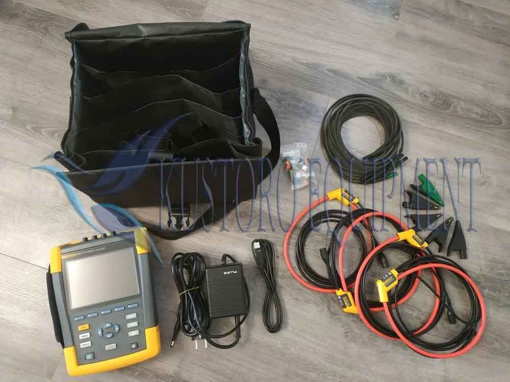
What’s in the Box
- Side strap
- Hang strap
- Battery pack
- 8GB SD card
- Decal set
- Alligator clips
- 2.5m test leads
- Flexible current probe (6000A AC)
- USB cable
- Power adapter
- Plug adapter set
- Safety booklet
- Manuals (CD)
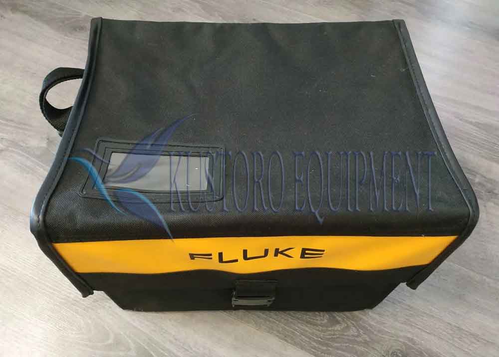
- Soft case
Additional information
| Lead Time | 5-7 days |
|---|---|
| Packaging | Box |
Brand
Fluke


Reviews
There are no reviews yet.